However, about all the guides seemed to use the larger Raspberry Pis, like A or 3, and I had only the wireless Raspberry Pi zero W model. The guides didn't work out directly, but luckily I got it to work in the end and here I describe how.
Another plus side is that the zero W uses wifi connection, so I got wireless debugging over wifi, which is great since my project is mains powered, and now I can flash and debug safely without risk of electic shock!
STM32 connection
I designed in a very simple debug connection to the project. The SWD pins are routed directly from the processor to the debug connector, together with the reset pin. Following figures show the schematic I used for the debug connection. |
| SWD connector with series resistors for ESD and noise protection |
 |
| SWD data and clock pins directly go to the processor |
 | ||
| Reset pin is also directly connected to the processor |
Raspberry Pi zero W connection
The guides, like the ones I linked in the beginning, use RPi pins (BCM) 18, 24 and 25 and a "native" OpenOCD configuration. I couldn't get that to work so I selected following pins that are used with a "sysfsgpio" configuration: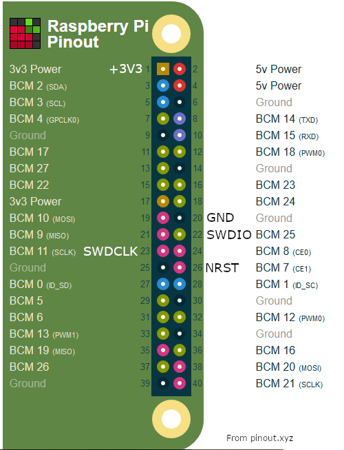 | |
| Raspberry Pi zero W pins used for SWD |
 |
| Debug connection between the boards |
OpenOCD configuration
The OpenOCD configuration was the most critical part! I had plenty of issues before I understood how to make the reset configuration. In the beginning, the flashing worked fine but the start address after reboot was wrong so the micro did start only randomly.I needed to change the sysfsgpio-raspberrypi.cfg located at /usr/share/openocd/scripts/interface/ to following:
#
# Config for using RaspberryPi's expansion header
#
# This is best used with a fast enough buffer but also
# is suitable for direct connection if the target voltage
# matches RPi's 3.3V
#
# Do not forget the GND connection, pin 6 of the expansion header.
#
interface sysfsgpio
# Each of the JTAG lines need a gpio number set: tck tms tdi tdo
# Header pin numbers: 23 22 19 21
sysfsgpio_jtag_nums 11 25 10 9
# Each of the SWD lines need a gpio number set: swclk swdio
# Header pin numbers: 23 22
sysfsgpio_swd_nums 11 25
# If you define trst or srst, use appropriate reset_config
# Header pin numbers: TRST - 26, SRST - 18
# sysfsgpio_trst_num 7
# reset_config trst_only
# sysfsgpio_srst_num 24
sysfsgpio_srst_num 7
reset_config srst_only srst_push_pull
# or if you have both connected,
# reset_config trst_and_srst srst_push_pull
The most important part was the sysfsgpio_srst_num 7 and reset_config srst_only srst_push_pull. With trst the reboot did not work properly. Only after I figured the correct reset config, did the micro start to reboot at the correct address at the beginning of flash memory!
Other thing was to do an OpenOCD config file openocd.cfg:
source [find interface/sysfsgpio-raspberrypi.cfg]The first line tells to use the correct, already modified, interface configu. Then there is the source line telling the type of processor. And also in this config I have some reset config flags.
transport select swd
set WORKAREASIZE 0x2000
source [find target/stm32f0x.cfg]
reset_config srst_only srst_nogate
adapter_nsrst_delay 100
adapter_nsrst_assert_width 100
bindto 0.0.0.0
init
targets
reset halt
Also important line is the bind 0.0.0.0 which tells OpenOCD to allow connections from external interfaces (wifi). Otherwise only localhost is allowed, and the debugging over wifi won't work.
The OpenOCD must be started in the same directory where the openocd.cfg is located, with sudo opencd command.
Eclipse configuration
I won't go into details on how to configure Eclipse to be used with STM32, it was quite a pain in the ass to get to work. There are multiple guides on the 'net on the topic, one should follow those.To get the OpenOCD debugger to work, I think I followed this guide. Most important part is to uncheck the "Start OpenOCD locally" setting, and fill in correct IP address and port of the RPi in the debug configuration.
Following figure shows the configuration I have.
 | |
| Parameters for remote OpenOCD connection |
 | |
| Remote debugging the mains powered equipment |