Mono receiver
As shown in the above examples, receiving the basic (mono) FM broadcast is very straightforward. The radio receiver is first tuned to correct center frequency with high enough sampling rate, e.g. 2 Mbps. The signal is then low-pass filtered at around 80...100 kHz so that only the relevant part is left. After filtering, the signal can be FM-demodulated. As described e.g. in Wikipedia, the FM deviation is 75 kHz.After demodulating the signal, it needs to be low-pass filtered to discard everything but the audio. The bandwidth is 15 kHz, so that is a suitable filter corner frequency. Then the signal just needs to be resampled to e.g. 48 kHz and played out from speakers. Here is my take on the mono FM receiver in GRC. The .grc file can be found from my GitHub.
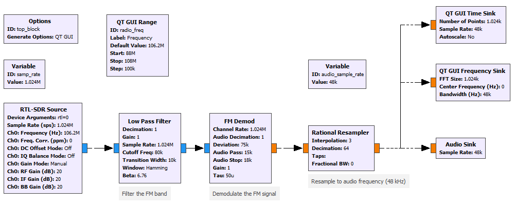 | |||
| Mono FM receiver |
 |
| GRC window for FM mono receiver |
What about stereo?
So, if receiving mono radio was that simple, receiving stereo cannot be much harder, right? Well actually there is quite some more details that needs to be handled. I didn't really find any good examples on how to do it so I had to study the FM specification as well as GRC to get it done.The complete spectrum of the demodulated FM radio broadcast looks like following (simplified, generated by my python script which I'll explain later):
 | ||
| Demodulated FM broadcast spectrum |
- Red: 30 Hz ... 15 kHz is the mono signal. A stereo signal is converted to mono by summing both channels, i.e. mono = left + right
- Green: 19 kHz pilot signal. This indicates a stereo broadcast and is important for stereo receiving for other reasons too.
- Yellow: 23 ... 38 ... 53 kHz "Stereo" signal. The difference of left and right channels (left-right) is sent here. The difference signal is amplitude modulated to a 38 kHz carrier.
- Orange: 55 ... 57 ... 59 kHz Radio Data System (RDS) signal is sent around 57 kHz, taking something like 4 kHz band. We might return to this in later parts.
| Stereo FM modulation equation (from Wikipedia) |
![\left[0.9\left[{\frac {A+B}{2}}+{\frac {A-B}{2}}\sin 4\pi f_{p}t\right]+0.1\sin 2\pi f_{p}t\right]\times 75~\mathrm {kHz}](https://wikimedia.org/api/rest_v1/media/math/render/svg/352564238bba8445f52cd99f8919979aece6ca39)
After the 38 kHz carrier is regenerated, the demodulation can be done simply by multiplying the signal with the carrier, and applying a low pass filter again.
Basic concept for stereo receiving
I came up with following procedure to receive the stereo FM broadcast:- FM demodulate the signal, without low-pass filtering (raw signal)
- From the raw signal, low pass filter with 15 kHz filter the mono (L+R) signal
- From the raw signal, bandpass filter the 19 kHz pilot tone
- Use PLL to recover a clean, phase correct pilot with amplitude of 1.0
- Square the PLL output and bandpass filter it at 38 kHz to get the second harmonic
- Multiply the raw signal with the now regenerated carrier and low pass filter with 15 kHz filter ("stereo" signal)
- Add the mono and "stereo" signals together to reconstruct the left channel
- Subtrack the mono and "stereo" signals to reconstruct the right channel
- Resample properly to get a 48 kHz audio signal
Python helper
Since it is necessary to recreate the pilot tone and the 38 kHz carrier with correct phase, I wrote a python script that creates a baseband signal (what the FM demodulator would output) as a wav file. Then in GRC I can replace the FM demodulator block with a waveform source and use that to develop the receiver. Since the output of the right side resampled went to multiple blocks, I decided to just resample the wav file to higher sample rate for simplicity. |
| Rtl-sdr and FM demodulator are disabled and replaced with waveform source |
The benefit of this approach is that I know exactly what kind of signals to expect and what is the phase shift between the clocks and the different signals is, and I can easily check whether everything works correctly, e.g. if any filters add phase shift or if some gains are wrong.
In the following part I will show comparison of the output of the python script and what is the output of the GRC receiver.
Note about the de-emphasis
After I got the receiver to work, I had some issues with the stereo signal gain. I had to boost the difference channel gain to something like 30 to get good stereo separation even though there should be no need for additional gain. Turns out the reason was de-emphasis.FM radio broadcast uses something called pre-emphasis to boost high frequency signals to increase the signal-to-noise ratio. The receiver then applies a de-emphasis, low-pass filter, to restore the original signal. The FM demodulator block in GRC has a "tau" to set the time constant of the de-emphasis filter.
However, only after noticing a detail in figure 3 in this pdf file, I figured out what was going on.
 | ||
| Figure 3 from the pdf file, emphasis mine |
After this I also added the pre-emphasis to my python script.
In the second part I will explain how I made the stereo receiver.
Ei kommentteja:
Lähetä kommentti